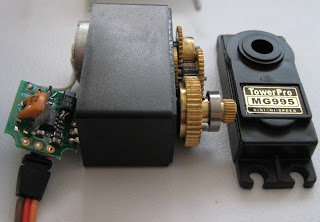
Now lets break it open and work out what the nitty gritty bits inside are. The servos are labeled as "digi", which some take to mean digital. There are discussions on RC forums about these servos and if they are actually digital and how good they are. Apparently digital servos are better - better holding torque, less dead band and more responsive. The forum concensus was that they wern't digital (because digital servo's should be expensive). I'm not into my RC vehicles so I don't know much about servos, but I am a trained electronic engineer. As we shall soon see these servos are in fact digital (and i'd suggest that analogue servos would be more expensive).
 Inspecting the circuit board inside we find:
- three SOIC-8 ICs (5 in the big brother) which have had their marking removed (thanks Mr Manufacturer guy),
- a couple of electrolytic capacitors,
- some surface mount capacitors and resistors,
- an 8MHz ceramic resonator,
- a couple of transistors,
- a 3.3V linear voltage regulator.
The transistors provide the inverted full supply voltage drive signals to the P-type MOSFETs.
The final component of question is the 'contol' IC. In an attempt to protect the design the top of the IC has been scraped to remove the markings. I suspect the IC is a microcontroller.
The micro's pins are connected to:
Pin 1. VCC
Pin 2. Oscillator
Pin 3. Oscillator
Pin 4. H-bridge control
Pin 5. Servo's PWM control input wire
Pin 6. H-bridge control
Pin 7. Potentiometer input (ADC?)
Pin 8. GND
The micro is probably a PIC, since they are cheap and well known. After a bit of internet searching the pin-out matches the 8-pin microcontrollers of the 12-series PICs. The PIC12F510 being the most likely.
No comments:
Post a Comment