If you are writing a piece of code, especially for other peoples use, think about how you name it. Does it make sense? I have just wasted several hours chasing a bug in some VHDL for an Altera Cyclone III. I want to force the use of carry chains; to inform the synthisizer, pass the signals through a CARRY_SUM buffer that has the ports (Sin, Cin, Sout, Cout). There are a few rules that must be followed for the input logic functions of the signals.
rant begin
Why did the engineer who constructed the CARRY_SUM buffer, put the ports in the opposite order; sum then carry. This engineer has single handedly wasted three hours of my life and I shudder to think how many other people have had the same problem.
end rant;
Unfortunately this is set in stone now, no way to change it, here to annoy me forever. I've posted this in the hope that it will have saved you some precious time, because I couldn't find the solution anywhere else on the interwebs, probably because it makes you feel stupid when you do find the issue and don't want to admit it, hence the rant (it wasn't my fault).
Thursday, September 24, 2009
Monday, April 27, 2009
Compiling the physics abstraction layer (PAL) with the BULLET physics engine
So I have an aquatic robotics project I am working on where I want to build a physics simulation for testing my control code. The robot itself is quite large and requires a large amount of space to operate in, i.e., open ocean and is currently in another city. This all makes testing and experimentation difficult. Therefore I am going to build a physics simulation that will emulate the robot on my laptop so I can do development at my leisure, and without getting water and sand in my beautiful laptop.
So to start with I need to select a physics engine and compile it for my computer running Ubuntu Jaunty 9.04 64-bit. I have chosen to use the Physics Abstraction Layer (PAL) since it looks relatively easy to use and includes some buoyancy functionality (which I intend to improve). It requires an actual physics engine back end, there are many to choose from such as ODE, Tomahawk, Box2D, .... I have chosen the BULLET physics engine.
Now to set up the programming environment. How to compile and build PAL physics abstraction layer with the BULLET physics engine on Linux. The lines starting with a $ are to be executed on the command line.
Get the Subversion source control client (svn):
Install the Bullet libraries to /usr/local/lib/ and the Header files to /usr/local/include/bullet/
Do not use the premake instructions for building PAL. I believe they are old. Use the Cmake system instead.
Some more variables will be shown in the main window.
Click Generate. This will setup the project for you.
Now make a few quick edits to get the demo to work. In pal/Config.h change the default engine from "BULLET" to "Bullet". In pal/example/begin.cpp change line 7 from PF->LoadPALfromDLL(); to PF->LoadPALfromDLL("/usr/local/lib/"); so it know's where to find the Bullet physics libraries.
Now compile it.
So to start with I need to select a physics engine and compile it for my computer running Ubuntu Jaunty 9.04 64-bit. I have chosen to use the Physics Abstraction Layer (PAL) since it looks relatively easy to use and includes some buoyancy functionality (which I intend to improve). It requires an actual physics engine back end, there are many to choose from such as ODE, Tomahawk, Box2D, .... I have chosen the BULLET physics engine.
Now to set up the programming environment. How to compile and build PAL physics abstraction layer with the BULLET physics engine on Linux. The lines starting with a $ are to be executed on the command line.
Get the Subversion source control client (svn):
$ sudo apt-get install subversionCheckout read-only copies of PAL and BULLET from svn:
$ svn co https://pal.svn.sourceforge.net/svnroot/pal/pal palGet some of their dependencies:
$ svn checkout http://bullet.googlecode.com/svn/trunk/ bullet-read-only
$ sudo apt-get install freeglut3 freeglut3-dev cmake g++ cmake cmake-gui libsdl1.2-devCompile BULLET.
$ cd bullet-read-onlyEdit install.sh, replacing all Window's line endings (\r\n) with UNIX line endings (\n)
$ gedit install.sh &
Menu->Search->Replace, Search for \r\n, Replace with \n, click Find. Save, Quit.
$ ./autogenIf you have a multicore CPU then include the --enable-multithreaded option. It may give you better real-time performance.
$ ./configure --enable-multithreadedCompile using make.
$ make -j 2The -j 2 option tells make to do two jobs at once, i.e., use two CPU cores.
Install the Bullet libraries to /usr/local/lib/ and the Header files to /usr/local/include/bullet/
$ sudo make installI had to manually copy the btActionInterface.h file to get PAL to compile, it appears it was left out of the install script.
$ sudo cp src/BulletDynamics/Dynamics/btActionInterface.h /usr/local/include/bullet/BulletDynamics/Dynamics/Compile PAL.
Do not use the premake instructions for building PAL. I believe they are old. Use the Cmake system instead.
$ cd ../pal/Open the Cmake GUI
$ cmake-gui &Enter the source and build directories at the top to the current directory (pal). The window below will list a bunch of variables. Select the tick box for PAL_BUILD_BULLET. Click "Configure". A window will show up. Select the default Unix make file option.
Some more variables will be shown in the main window.
- Set the BULLET_SINGLE_THREADED if you didn't build the multi-threaded version before.
- Fix the BULLET_INCLUDE_DIR -> /usr/local/include/bullet and the
- BULLET_LIBRARY_??? variables -> /usr/local/lib/lib???.so if they haven't been found.
- Change from simple view to advanced view and find the CMAKE_CXX_FLAGS variable and add -fPIC to it.
Click Generate. This will setup the project for you.
Now make a few quick edits to get the demo to work. In pal/Config.h change the default engine from "BULLET" to "Bullet". In pal/example/begin.cpp change line 7 from PF->LoadPALfromDLL(); to PF->LoadPALfromDLL("/usr/local/lib/"); so it know's where to find the Bullet physics libraries.
Now compile it.
$ make -j 2And install it.
$ sudo make installTell the operating system about the new libraries.
$ sudo ldconfigNow we should be able to test the demo/test program. It has been compiled into the bin/ directory. Run it.
$ bin/palbeginnerShould get output like:
Found dll 'liblibpal_bullet.so'Fin.
Found dll 'libbulletmultithreaded.so'
Found dll 'libbulletcollision.so'
Found dll 'libbulletdynamics.so'
Found dll 'libbulletmath.so'
Found dll 'libbulletsoftbody.so'
Physics:0x16e0840
Current box position is 1.49902 at time 0.01
Current box position is 1.49706 at time 0.02
Current box position is 1.49412 at time 0.03
Wednesday, October 15, 2008
Waving Hello World
We have servo action as can be seen in the video above. I have written some code to read the ADC, calculate a PID control and provide a PWM signal to the motor. This all comes together to move the position read by the ADC to the set-point, which is moved backwards and forwards to make the servo wave. This is all done with 8-bit integers, however the ADC gives a 10-bit result, so next task will be to make it work with 16-bit integers - giving it 4-times the accuracy.
I've had a few hiccups along the way.
The first was a problem with the piklab-prog program that loads the PIC through the ICD2 programmer. In short it was writing the contents of the last memory address 0x3FF(the oscillator calibration word) back to the memory location 0xFF, overwriting what was there. So I filed a bug report and reluctantly moved development to a windows machine.
The second is choosing a C compiler for the PIC. Hitech is a commertial compiler company that write compilers for the PIC. They seem like they should work well. They provide a free compiler PICC lite, but this doesn't do any optimisation - you have to pay for that. Buy you can use a 45 day trial of the optimisang standard version PICC std. It is also available for linux which is nice.
Third problem is one that had me bamboozled for a couple of days. I was working on the PWM H-bridge control. The left side is controlled by one GPIO1 and the right by GPIO2. The motor would spin fine in one direction but not in the other and causing the MOSFETS to heat up quickly. Having a look at the signals on an oscilloscope revealed that when GPIO1 was written high, it would go high for one instruction cycle but not stay high. This had the effect of making the mosfet switch on and off very quickly and hence the heat. After talking to Phil at uni he suggested that I was writing to the second pin too quickly (which I was - in the next instruction in fact). The problem is that the PIC operates with a read of the port, modification of the pins, and a write back. The read of the next instruction occurs just after the write of the last instruction. The write is delayed by the capcitance on the pin or other factors so the read of the port (which read the values of the pins) got the wrong value (one without the recently modified pin). This is called a RAW (Read after Write) hazard. To fix this you need to do something in between or modify both at the same time.
And finally I'll end with the question of using a sigma-delta modulated output for control? Since the PWM at best runs at only 100Hz, not giving very precise control of the motor, maybe a sigma-delta type control would be better. It would have a "variable frequency" higher than 100Hz, fast response to a change in the servo position. It would also be smoother on the powersupply with several servos on the same bus with synchronised PWM.
Monday, September 15, 2008
Time Pieces
I have a little fascination with time pieces, not your regular clocks though, but interesting ways to display the time. Every now and then I think of a new idea (or find one on the net) that I think would be cool to have sitting on my desk.
The Nixie clock. I have a bunch of nixie tubes that i scavenged from a 1960's calculator. A nixie tube is what ws used for electronic displays before the 7-segment led came along. They are neon lights with cathodes in the shape of the numbers 0-9. When you apply ~200V between the cathode and annode the neon glows an awesome orange colour around the cathode. The difficulty with this project is the high voltages required.

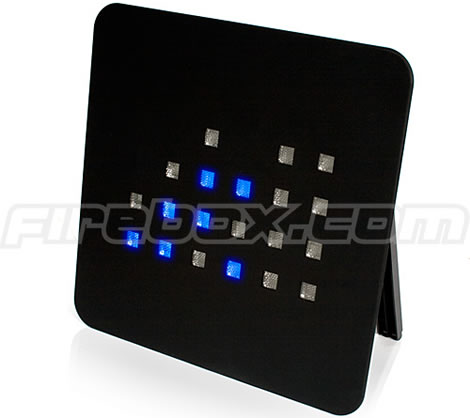
The Binary Clock. Simply six columns of upto 4 led's that light up with binary numbers. Simple, but you have to be a bit of a geek to read and appreciate it.
Volumetric Display Clock. A 5x5x5 cube of RGB leds. Can display alot of cool patterns on it but also the time in a number of ways.
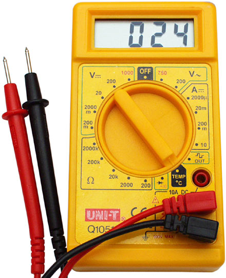
 Multi-meter clock. And my latest idea, have a microcontroller generate three voltages that extend to three test points labeled Hours, minutes and seconds. By probing with a multimeter you can discover the time.
The Nixie clock. I have a bunch of nixie tubes that i scavenged from a 1960's calculator. A nixie tube is what ws used for electronic displays before the 7-segment led came along. They are neon lights with cathodes in the shape of the numbers 0-9. When you apply ~200V between the cathode and annode the neon glows an awesome orange colour around the cathode. The difficulty with this project is the high voltages required.
The Binary Clock. Simply six columns of upto 4 led's that light up with binary numbers. Simple, but you have to be a bit of a geek to read and appreciate it.
Volumetric Display Clock. A 5x5x5 cube of RGB leds. Can display alot of cool patterns on it but also the time in a number of ways.
Multi-meter clock. And my latest idea, have a microcontroller generate three voltages that extend to three test points labeled Hours, minutes and seconds. By probing with a multimeter you can discover the time.
Tuesday, September 9, 2008
Software Plan - First Run
Minimum specifications:
At startup:
- Use the existing hardware.
- Run at 4MHz = 1MIPS on the internal RC oscillator to free up two extra pins.
- Servo communications,
- Bit bash a one-wire serial communications protocol,
- based on dallas 1-wire bus?
- Bit bash a two wire bus (maybe easier),
- I2C.
- Traditional servo pulse width command.
- Each Servo individually addressable,
- 255 unique addresses 0x00 - 0xFE,
- one broadcast address 0xFF.
- Servo action - position control,
- PID controller,
- Adjustable P, I and D gains.
- Other controller (LQR?).
- Dead band adjustment.
- PWM power control for motor.
- Debug LED(s).
- Store configuration in EEPROM (128 bytes),
- Address.
- Controller gains.
- Control limits,
- Position extremes.
- Torque\Current extremes.
- Home Position.
- Current sensing,
- additional current sensing amp hardware required.
- use additional ADC pin (GP4).
- Constant torque controller.
At startup:
- Load the configuration data from EEPROM data memory into RAM.
- Configure device.
- GPIO, GP1 and GP2 output (H-bridge).
- GPIO, GP4 and GP5 (comms).
- ADC, GP0 input (Pot).
- TIMER0 (8bit, 1MHz, prescaler 1,2,4,8,16,32,64,128,256) for PWM.
- TIMER1 (16bit, 1MHz, prescaler 1,2,4,8) for Comms.
- If startup bit START_CONTROL set then initialise control to "home position", else disable motor.
- Initialise communications protocol, begin listening for address.
Friday, September 5, 2008
Series Hybrid Electric Tandem Bicycle
So I'm going to take a ride on the alternative transport band wagon with this idea. My girlfriend and I try and cycle most places, unfortunately she is about half my size and I'm twice as fast as her. Solution: a tandem bicycle. Only she worries that she won't be able to contribute to the propulsion because we are so mismatched, I pedal too fast or use a different gear than she would use or something. So I thought - you need independent drive trains. And of course, being an electrical engineer I turn to electronics to solve my problem.
Why not, instead of the pedals driving a gear set, have them coupled to a low speed generator. Then from each pedal gen-set combine the power produced using a couple of power electronic converters to match the voltages onto a common DC bus. From there a third power-converter could run a heafty hub motor at the rear wheel (and the front too). A fourth converter could be used to attach a battery to the system and provide energy storage absorbed from excess human effort and regenerative braking and depleted for use uphill and takeoff.
The pedal generators could be controlled to provide a constant cadence and torque, individually adjustable to suit the cyclists. One problem is that the RPM is quite low ~ 60-100 rpm. Since the voltage generated is roughly proportional to the speed of the generator (change of flux inside the generator windings) a multi-pole machine should be used (more than the usual two to four). The torque at the generator shaft is proportional to the current.
One final benefit to a series hybrid bike. There is no dirty chain or temperamental derailer to deal with. Just simple, maintenance-free and clean electrons.
It's unlikely that i'll get around to building this. However I have spoken to my supervising lecturer and he is going to offer it as a final year engineering project next year. So I may still get to ride it.
Friday, August 29, 2008
It's Alive!

LEDs are a flashing. How exciting! Nothing gets a hardware engineer going like a couple of flashing LEDs. It symbolises success. Half the battle is won when you can program a piece of hardware to flash some LEDs. It means that you:
- Soldered the major components correctly,
- Have a working power supply,
- Have a tool chain for compiling programs for the hardware,
- Have a method for downloading the code to the hardware.
So I removed the 8MHz resonator connected to pins 2 and 3, not needed since the PIC has an internal RC oscillator. I soldered two LED resistor pairs between ground and pins 2 and 3 respectively. I then grabbed some assembly code from this site, and modified it to output to the two LEDs alternately. It is listed here:
; An LED Blinker
list p=12f675
include "p12f675.inc"
__CONFIG _CPD_OFF & _CP_OFF & _BODEN_OFF & _MCLRE_OFF &_PWRTE_OFF & _WDT_OFF & _INTRC_OSC_NOCLKOUT
small_delay_tmp equ 0x20
long_delay_tmp equ 0x21
goto main
small_delay:
movlw 0xff
movwf small_delay_tmp
small_delay_L1:
decfsz small_delay_tmp, F
goto small_delay_L1
return
; ----------------------------
; W contains count on entry.
; Store it in a temp variable.
; Keep on decrementing and
; calling small_delay
; ----------------------------
long_delay:
movwf long_delay_tmp
long_delay_L1:
call small_delay
decfsz long_delay_tmp, F
goto long_delay_L1
return
; ----------------------------
; The main LED blinker
; ----------------------------
main:
bcf STATUS, RP0
clrf GPIO
movlw 0x7
movwf CMCON ; disable comparator
bsf STATUS, RP0
movlw 0x0
movwf TRISIO ; All pins outputs
bcf STATUS, RP0
infinite:
bcf GPIO, GP5
bsf GPIO, GP4
movlw 0xFF
call long_delay
bsf GPIO, GP5
bcf GPIO, GP4
movlw 0xFF
call long_delay
goto infinite
end
I assembled it through piklab with gpasm from gputils. I then downloaded it through the ICD2 programmer again using piklab, configured so that the board is powered through the ICD2 (it doesn't seem to work otherwise). Amazingly the LED's flash, just like they are supposed to. Yay.
I'm not a fan of programming in assembler, so I'm going to try a couple of C compilers like SDCC. Unfortunately the PIC12F675 has only 1 kwords (1 word = 14 bits = 1 opcode) of program space, so to getting a C program to fit maybe a challenge. But why not try.
I'm not a fan of programming in assembler, so I'm going to try a couple of C compilers like SDCC. Unfortunately the PIC12F675 has only 1 kwords (1 word = 14 bits = 1 opcode) of program space, so to getting a C program to fit maybe a challenge. But why not try.
Subscribe to:
Posts (Atom)