About this Blog

This blog is an engineering log book; for me to record the progress on my many projects and hopefully to inspire you.

Some projects do not get off the ground, they remain as interesting thoughts, a select few get some work done on them, even fewer get close to completion, and none get completed because unfortunately I subscribe to the theory: "If something ain't broke then it doesn't have enough features". If you'd like to collaborate on some work to get something to a useable state then send me some communications.

Being a blog, posts are listed in chronological order. However I usually have multiple projects on the go and will try to post some of my earlier work. With this in mind I'll try to add labels to each post so all posts relevant to one project can be easily extracted.

Enjoy and happy hacking.

Monday, September 15, 2008

Time Pieces

I have a little fascination with time pieces, not your regular clocks though, but interesting ways to display the time. Every now and then I think of a new idea (or find one on the net) that I think would be cool to have sitting on my desk.

The Nixie clock. I have a bunch of nixie tubes that i scavenged from a 1960's calculator. A nixie tube is what ws used for electronic displays before the 7-segment led came along. They are neon lights with cathodes in the shape of the numbers 0-9. When you apply ~200V between the cathode and annode the neon glows an awesome orange colour around the cathode. The difficulty with this project is the high voltages required.


The Binary Clock. Simply six columns of upto 4 led's that light up with binary numbers. Simple, but you have to be a bit of a geek to read and appreciate it.

Volumetric Display Clock. A 5x5x5 cube of RGB leds. Can display alot of cool patterns on it but also the time in a number of ways.
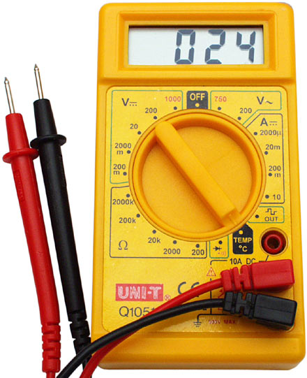
Multi-meter clock. And my latest idea, have a microcontroller generate three voltages that extend to three test points labeled Hours, minutes and seconds. By probing with a multimeter you can discover the time.

Tuesday, September 9, 2008

Software Plan - First Run

Minimum specifications:
  • Use the existing hardware.
  • Run at 4MHz = 1MIPS on the internal RC oscillator to free up two extra pins.
  • Servo communications,
    • Bit bash a one-wire serial communications protocol,
      • based on dallas 1-wire bus?
    • Bit bash a two wire bus (maybe easier),
      • I2C.
    • Traditional servo pulse width command.
  • Each Servo individually addressable,
    • 255 unique addresses 0x00 - 0xFE,
    • one broadcast address 0xFF.
  • Servo action - position control,
    • PID controller,
      • Adjustable P, I and D gains.
    • Other controller (LQR?).
    • Dead band adjustment.
  • PWM power control for motor.
  • Debug LED(s).
  • Store configuration in EEPROM (128 bytes),
    • Address.
    • Controller gains.
    • Control limits,
      • Position extremes.
      • Torque\Current extremes.
    • Home Position.
Optional features:
  • Current sensing,
    • additional current sensing amp hardware required.
    • use additional ADC pin (GP4).
  • Constant torque controller.
Design Overview:
At startup:
  1. Load the configuration data from EEPROM data memory into RAM.
  2. Configure device.
    1. GPIO, GP1 and GP2 output (H-bridge).
    2. GPIO, GP4 and GP5 (comms).
    3. ADC, GP0 input (Pot).
    4. TIMER0 (8bit, 1MHz, prescaler 1,2,4,8,16,32,64,128,256) for PWM.
    5. TIMER1 (16bit, 1MHz, prescaler 1,2,4,8) for Comms.
  3. If startup bit START_CONTROL set then initialise control to "home position", else disable motor.
  4. Initialise communications protocol, begin listening for address.

Friday, September 5, 2008

Series Hybrid Electric Tandem Bicycle

So I'm going to take a ride on the alternative transport band wagon with this idea. My girlfriend and I try and cycle most places, unfortunately she is about half my size and I'm twice as fast as her. Solution: a tandem bicycle. Only she worries that she won't be able to contribute to the propulsion because we are so mismatched, I pedal too fast or use a different gear than she would use or something. So I thought - you need independent drive trains. And of course, being an electrical engineer I turn to electronics to solve my problem.

Why not, instead of the pedals driving a gear set, have them coupled to a low speed generator. Then from each pedal gen-set combine the power produced using a couple of power electronic converters to match the voltages onto a common DC bus. From there a third power-converter could run a heafty hub motor at the rear wheel (and the front too). A fourth converter could be used to attach a battery to the system and provide energy storage absorbed from excess human effort and regenerative braking and depleted for use uphill and takeoff.

The pedal generators could be controlled to provide a constant cadence and torque, individually adjustable to suit the cyclists. One problem is that the RPM is quite low ~ 60-100 rpm. Since the voltage generated is roughly proportional to the speed of the generator (change of flux inside the generator windings) a multi-pole machine should be used (more than the usual two to four). The torque at the generator shaft is proportional to the current.

One final benefit to a series hybrid bike. There is no dirty chain or temperamental derailer to deal with. Just simple, maintenance-free and clean electrons.

It's unlikely that i'll get around to building this. However I have spoken to my supervising lecturer and he is going to offer it as a final year engineering project next year. So I may still get to ride it.